
VHF Direction Finding (VDF) is a well-established radio navigation technique used to determine the direction of a Very High Frequency (VHF) radio transmission. It plays a crucial role in aviation and maritime navigation, enabling the rapid identification of a transmitter’s direction and, when combined with multiple stations, its exact location. For decades, VDF has been one of the most practical tools for enhancing situational awareness and improving the safety of air traffic management.
The principle is simple: by analyzing how a radio signal arrives at an antenna array, the system can calculate the bearing (azimuth) of the transmission source. For pilots, air traffic controllers, and navigators, this provides invaluable assistance in determining position, resolving uncertainty, and enhancing communication reliability.
VHF Direction Finding (VDF)
Definition
Radio Direction-Finding: A radiodetermination method that uses the reception of radio waves to determine the direction of a transmitting station or object.
Source: ICAO Annex 10, Volume II (originally defined by the International Telecommunication Union – ITU and later incorporated by ICAO).
Note: Radio direction-finding is an umbrella concept encompassing various techniques across different frequency bands. In aviation, VHF Direction Finding (VDF) is the most widely recognized, since VHF remains the primary medium for air–ground communications in civil aviation.
System Description
A VHF Direction Finder (VDF) is a ground-based navigation aid composed of the following elements:
Directional Antenna System
An array of antennas arranged in a specific configuration (e.g., Adcock or Watson–Watt systems).
The arrangement allows the system to compare the signal’s arrival from multiple directions.
VHF Radio Receiver
Tuned to the operational frequency of an Air Traffic Services Unit (ATSU).
The receiver processes signals transmitted by aircraft within range.
Signal Processing Unit
Analyzes variations in signal strength and phase.
Computes the azimuth (bearing) of the incoming transmission relative to the VDF station.
Operational Function
Single-Station Operation
Provides only the bearing of the transmitting source relative to the ground station.
Useful for giving pilots a directional reference (e.g., “Your bearing from the station is 085°”).
Multi-Station Operation
Two or more VDF stations may be linked.
Bearings from different locations are plotted to form a line of position.
The intersection of these bearings provides the exact position of the transmitter.
This is known as cross-bearing or triangulation.
Such flexibility makes VDF a versatile tool, especially in environments with limited radar coverage or as a backup to modern surveillance systems.
Frequency Range
Primary Band: VDF operates in the Very High Frequency (VHF) band (118 – 137 MHz), which is the standard communication range for civil aviation.
Other Bands:
UHF Direction Finders (UDF) work in the Ultra High Frequency range, often supporting state, defense, or military aviation operations.
Though the principle of direction-finding is universal, the VHF version dominates civil use due to its alignment with ICAO communication standards.
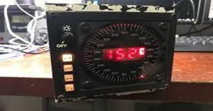
An example of a standalone VDF equipment is shown in the picture below:
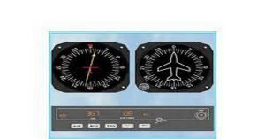
An example of VDF equipment integrated into the ATS system is shown in the picture below. The circle shows the estimated location of the received radio transmission.
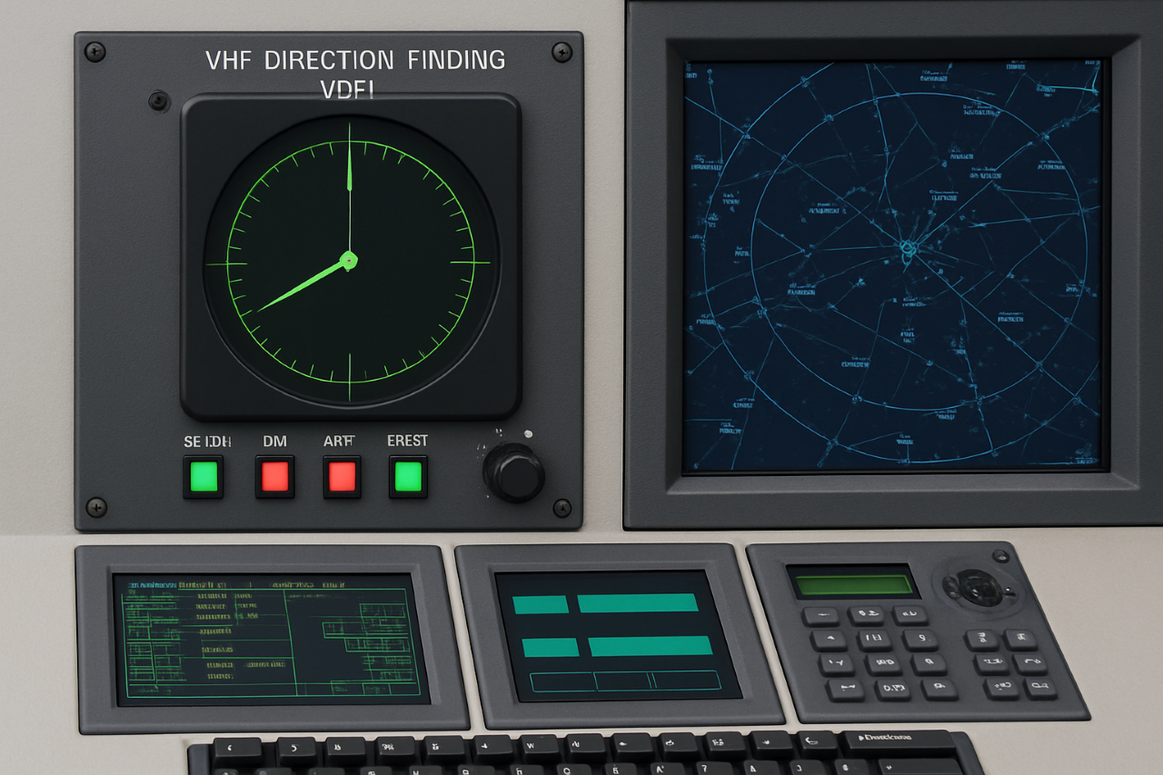
The controller receives a call from IVB3011. This traffic was not supposed to be on the frequency, hence it is represented in a dull (dark grey) color on the situation display.
However, as the green circle indicates the approximate position of the transmitting station, the controller’s attention is drawn to a specific, small part of the airspace and they can therefore easily assess the situation and take appropriate action.
Principle of Operation:
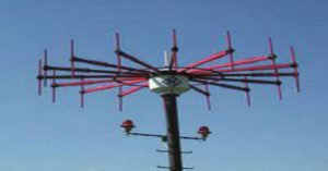
The receiving antenna of a VDF consists of several (3 or more) elements mounted around a pole.

Each element receives the same signal but at a slightly different time (i.e. they receive different phases at the same time). This allows the system to calculate the direction from which the signal has been received. An example of an antenna with three elements is shown below:

Principle of Operation – Phase Difference Method
The principle behind VDF involves determining the direction of the transmitting station by analysing the phase (time) difference of the received signal at multiple antenna elements.
Illustrative Example
- The antenna array is divided into six areas using dotted lines representing equidistant points from each antenna element.
- Signal reception sequence:
- The signal is received by element 1 first
- Then by element 2
- Finally by element 3
From this sequence:
- Since element 1 receives the signal before element 2 → the source is in Area II, III, or IV
- Since element 2 receives the signal before element 3 → the source is in Area I, II, or VI
- Since element 1 receives the signal before element 3 → the source is in Area I, II, or III
The only area satisfying all three conditions is Area II, meaning the aircraft is located east of the VDF station.
Real-World Implementation
- In actual systems, the precise phase differences are measured, allowing calculation of the exact bearing rather than just a general directional area.
- The number of antenna elements and the system design determine the accuracy of the bearing calculation.
ICAO Bearing Accuracy Classification
| Class | Accuracy |
| A | Within 2° |
| B | Within 5° |
| C | Within 10° |
| D | Worse than Class C |
ICAO Estimated Position Accuracy Classification (for VDF arrays)
| Class | Estimated Position Accuracy |
| A | Within 5 NM |
| B | Within 20 NM |
| C | Within 50 NM |
| D | Worse than Class C |
Applications of VHF Direction Finding (VDF)
VDF technology serves multiple operational and safety purposes in aviation, ranging from air traffic management to law enforcement.
1. Enhancing Air Traffic Controllers’ Situational Awareness
- VDF has been used for decades to help controllers determine the approximate position of an aircraft based on its radio transmissions.
- Standalone use: Even without integration, a VDF can provide a rough indication of the aircraft’s location.
- Integrated use: When connected to surveillance systems, VDF can identify which radar target made the last transmission.
- Historical method: In early radar systems with Plan Position Indicators (PPIs), a light strobe would flash from the centre of the radar display toward the transmitting aircraft.
- Modern method: Arrays of VDFs can display the approximate transmitter location on the situational display (e.g., by highlighting or circling it).
- Operational benefit: In busy airspace, especially where multiple aircraft have similar callsigns (e.g., flights from the same airline), this narrows the search area and reduces the need to scan the entire radar display.
2. Navigational Assistance
- Pilots can request bearing information from a ground-based VDF station.
- Bearings are provided as:
- QDM – Magnetic bearing to the station
- QDR – Magnetic bearing from the station
- This allows pilots to determine their position and direction of movement.
- True bearings can also be given, although they are less commonly used.
3. Homing
- Pilots may request a series of QDMs at intervals to fly directly toward a VDF station.
- Request intervals: Typically one minute apart at the start, increasing in frequency as the aircraft nears the station.
4. VDF Approach (PDF Approach)
- A type of instrument, non-precision approach
- Aerodromes with established VDF approaches are listed in national Aeronautical Information Publications (AIPs).
- Example: Cranfield Airport (EGTC) in the UK.
5. Locating Unauthorized Use of ATC Frequencies
- Law enforcement agencies can use VDF equipment to pinpoint the source of illegal or unauthorised transmissions on air traffic control frequencies.
Radiotelephony Procedures
Note: No standard ICAO phraseology is defined for VDF procedures. ICAO Annex 10 Vol. II contains general communication procedures when direction finding equipment is used. The phraseology in this section is derived from UK CAA CAP 413 Radiotelephony Manual.
For the aeronautical station to properly determine the bearing or position of an aircraft, the pilot may need to transmit a message of a specific length or more.
When providing a bearing or position information, the aeronautical station must specify the accuracy class.
Position information is provided as coordinates, degrees, and minutes are used followed by the words NORTH/EAST/SOUTH/WEST as appropriate.
The pilot must read back the information received for confirmation or correction.
Example:
- Pilot: TOWER, DVK1208, REQUEST QDM
- Controller: DVK1208, QDM 110 DEGREES, CLASS B
- Pilot: QDM 110 DEGREES, CLASS B, DVK1208
Related Articles
- Surveillance
- Identification
- Automated Direction Finder (ADF)
- Unauthorized Use of ATC Frequency
Further Reading
- ICAO Annex 10, Volume II, Chapter 6
- ICAO Doc 9426, Part III, Section 1, Chapter 6
- UK CAA CAP 413 Radiotelephony Manual
- EUROCONTROL: Radio direction finder (RDF) leaflet